In this post I will discuss about a simple animation of Spur Gears. I have used SW2009 for the tutorial but lower version can be used to perform this activity. You can use any cylindrical part for the animation. I have used spur gear to make the animation more realistic.
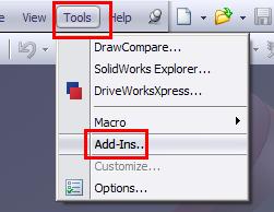
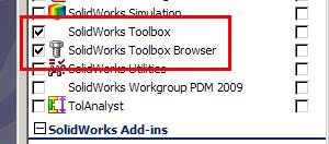
1. Start SolidWorks and go to Tools > Add-Ins. Make sure Toolbox/Toolbox browser is checked. If not then check them to add.
2. Click on the right side on Design Library and Select Toolbox. Next select Ansi Metric > Power Transmission > Gears. In side pane, you will see gears, racks, etc. RMB on Spur gear and select “Create Part”.

3. Set any properties of Spur Gear as desired. Click OK and then save your part.

4. Now click on “Make assembly from part/assembly” icon or File > Make assembly from part/assembly to start a new assembly.

5. Drop the gear anywhere in the assembly. It will get fixed by default.

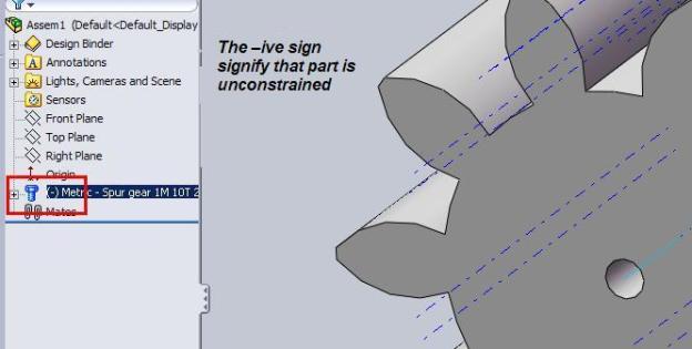
6. RMB on the part in the feature manager and select Float from the pop up window. This will remove the fix constraint from the part and make it free to move/rotate.

7. Now show the temporary axis by View > Temporary Axis. You can also use part axis if there is any to proceed.

8. After you have made the temporary axis on, the view will be like this.

9. Select the center axis as shown of the gear.
10. Select the appropriate plane (Front plane is this case) and click on Mate if it doesn’t pop up (as in pic) from the assembly toolbar.

11. Set a coincident mate between the selected plane (Front) and axis.
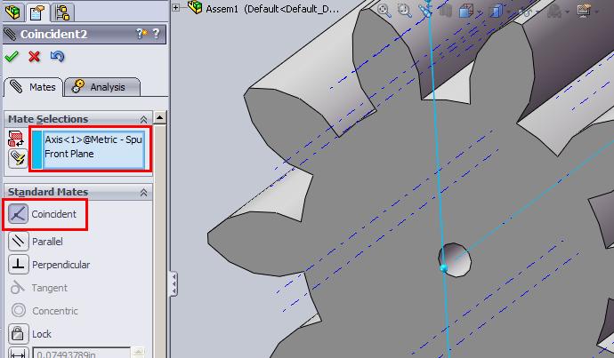
12. Select the same axis and another plane (Top plane in this case) and add another coincident mate.

13. Select the front face or back face of the gear and the left over plane (Right plane in this case) and set another coincident mate.
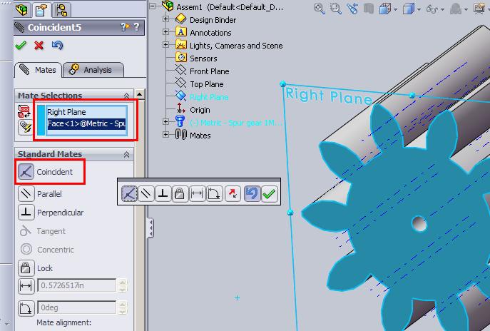
14. Now the part is constrained in such a way that it can rotate free around its axis. Check it by dragging the gear. You will see the rotary movement only.
15. Select the gear in the workspace or feature manager and drag it while keeping the Ctrl button pressed. This will create a copy of the gear.

16. Mate the front faces of both the gear by adding a coincident mate between them.

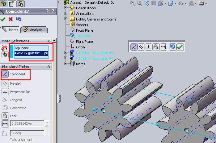
17. Select the center axis of second/copied gear and appropriate plane (Top plane in this case) and add a coincident mate.
18. Select the center axis of second/copied gear again and either a plane or center axis of first gear (I have selected Front plane) and add distance mate. I have given 10mm. You can set the position by flipping the direction.
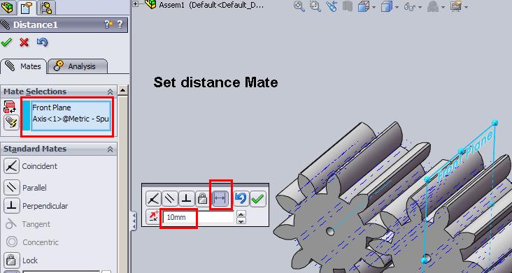
19. Now the second/copied gear is also free to rotate around its axis. Check this one also by dragging.
20. Set both the gear in an appropriate position as shown.

21. Click on Mate; go to mechanical mate and select gear mate.

22. Select the center axis or any other faces. I have selected the bore faces. Set the ratio to 1:1 as they are same gear and finally click OK. You can try with different sizes of gears.

Your gears are ready to animate. Try to drag any of the gear and see the other gear rotate. You can also add a rotary motor to animate the gears.
Click here: Gear Animation Files.zip
Pingback: How to Make a Human Camera – the Making of Touchy – ASH BLOG
Perfect, thank you so much :))
thanks a lot…. it was really what i want 🙂
Thank you very much for sharing. Your instructions are very clear.
Excellent!
i have a problem. i want to design a helical gear with module 0.75 and number of tooth 8.
but the tool box dialogue box shows only module 0.7 and number of tooth 10. how to rectify the problem.
i got a problem… i want to create a helical gear with number of tooth 8. but the minimum number of teeth is showing 10 in dialogue box. how to manage?
hi sir…
i need to design and animate a spiral gear…
how to design it? there is no option in tool box to design a spiral gear…
sir this is excellent tutorial.
but sir please give me some tutorial for chain & sprocket animation in solid works. please sir this is very urgent for me.
This was very helpfull,
thanks a lot 🙂
or in Polish we say : dziekuje 🙂
take care
Hi
I need some help regarding spur gears in Solidworks 2010.
I want to create a spur gear of module 0.3 mm and number of teeth 9. But the problem is that whenever I create a spur gear from the toolbox, the minimum number of teeth that can be obtained is 10.
Please provide me a solution to this.
There are two ways:
1 Edit the toolbox mdb (database file) and add the configuration.
OR
2 Get a machine hand book and model up the gear.
BTW there are few software available to model the gear like MITCALC and GEARTRAX
does this work for solidworks 2006? how do i get the addin for the gear? please email me if you’re available!
Yes it will work for SW2006 also. For gears you need to have Toolbox installed.
It was very helpful, Many thanks
Shafi
it was wonderful, Many thanks
Shafi
thanks for the tutorial,
Is that speed is proportional to the diameter
No both are independent. Well speed is not controlled in this tutorial.
If it was an bottom up assembly, why don’t you quickly build up the assembly using the parts again.
Otherwise, you can look for open surface in the save part and fill them up using surface tools and finally knit them to solid 🙂
Excelllent buddy!!!!
Thank you very much. This tutorial was very useful to me
Thanks for putting together this tutorial. Obviously, I’m not the only one who found it useful. About how long does it take you to create and animate your gear models?
Tony
Thanks Tony for your comments and I’m glad it was helpful. You just need few minutes to set the gears up and make them roll 🙂
thanks !! very helpful post!
Thanks buddy…..
It helped me a lot….
thanks once again….. 🙂
Hello, I´m beginning with RSS subscriptions. Now I can stay current with your site and especially the topic “How to animate simple Spur Gear in SolidWorks”
Thank you for the Information.
Pingback: Tips on Modelling a Rubber Track - 3DCADForums
Thanks a lot for this article! Really interesting.
Great article, great job! I’ve just added to my bookmark list. I’ll back for sure
For our project , we need an animation of the gear mechanism(gearbox).We have a helical pinion-gear and a bevel pinion-gear in the gearbox.At the end , we must convert the animation to a video file type.Which program would you suggest for this purpose?
Also , is it possible to add shafts and bearing to the animation file ?
thanks in advance
Everything can be done within SolidWorks, using Animator. Let me know if you need more help/details..
Hi..thanks for your reply..
Now we finished the term project numerically , i have values for “shaft diameter ” , “gear modules and teeth numbers” , “selected bearings and dimensions”..What do I need other than these? How to give the first motion ? and finally how to convert to video ?
thanks in advance
Are your 3d models ready??
What software you’ll be using to create the parts and assembly??
Hi deepak,
guess we are doing the same project with engine. We too found all the numeric data and we are trying to make an animation using SolidWorks. We inserted our helical gears on the screen from the toolbox menu, the pinion rotates but i can’t make the gear rotate. the pinion just moves through the gear. i been searching through web but couldn’t find anything yet..if you can help us.. thanks again..
Seems like your gear is fixed. Can you send a screen shot or the files..
Congratulations to me!! After more than 5 hours search i have found the menu to create gear :S
But unfortunately now SolidWorks gives error and shut down. I think there is no hope
Great Post!
Hi Deepak,
Can we get contact stress in between the rotating gears.
Shankar, sorry but I’m not expert with FEA stuff so can’t comment on this. But I check with FEA experts in my contact and get back to you.
I didn’t understand the concluding part of your article, could you please explain it more?
This article speaks about animating simple spur gears in SolidWorks. What more info you looking for??
Hi Deepak! You have a wealth of information here. Thanks for sharing your wisdom :-).
Keep up the good work
Thank you very much dude! this is exactly what i’ve been searching for
^^
thx it was a lot of help!
thanks for the help amigo!!!….I was able to do it with solidworks 2004…. I will try to do it with helical gears and see what happens….thank for sharing this info
Nice info….,
Thank you for helping………………excellent tutorial
Excellent guide. got my gears together in no time. the float command to unfix the first part in the assembly was especially useful.
This Gear Mate tutorial was very helpful to me.
Thank you very much.
Debra Sexton-Mohn