Do you ever need to show HALF Section views in the drawings??

Let’s discuss various ways to create them.
Using Section View
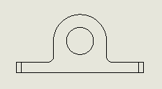
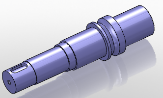
- Start a new drawing and insert a view.
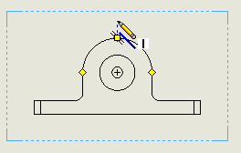
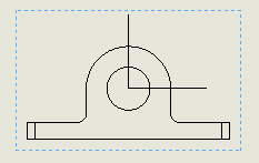
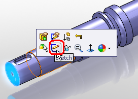
- Activate the view and insert an L shaped sketch. Using SW auto snap options start the sketch in line with the circle/arc quadrant or centre point.
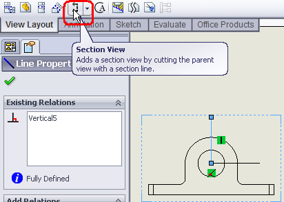
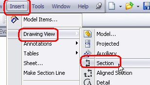
- Click on the line and select section view on view tool bar or Insert > Drawing Views > Section or right-click on sheet > Drawing Views > Section.
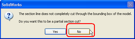
- Click NO on the prompt window for partial section.
- Place the section view on appropriate location.
- Now right-click on section view and select Isometric Section View.
- You may remove the section view label if required.


Using Configuration
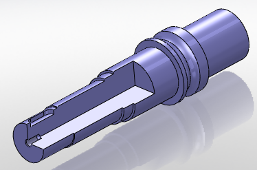
- Open the part for which you want to create the half section.
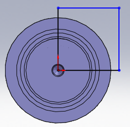
- Start a new sketch on the face/plane.
- Create a rectangular as shown.
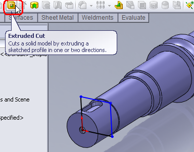
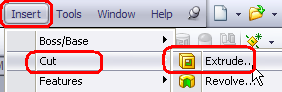
- Click on Extrude cut on feature tool bar or Insert > Cut > Extrude. You may or may not exit the sketch editor.
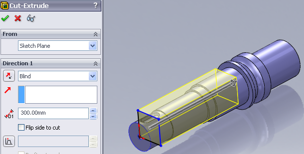
- Using any options, create the cut extrude feature.
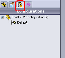
- Switch to configuration manager.
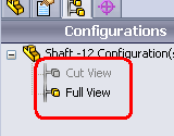
- Add a new configuration. I have added a Cut View named configuration. And renamed the other to Full View. You can give any name as desired/required.
- Activate the full view configuration and switch back to feature manager. Suppress the cut extrude feature we added above.
- Now we have Full View and Cut View configuration with no cut and cut.
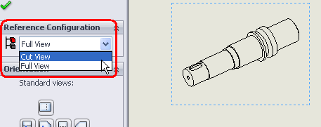
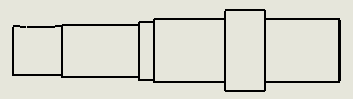
- Start a new drawing and place a view. Set the configuration to Cut View in case you don’t see the cut.
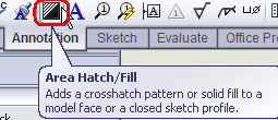
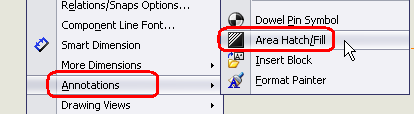
- Click on Area Hatch/Fill on Annotation toolbar or Insert > Annotations > Area Hatch/Fill or right-click on sheet > Annotations > Area Hatch/Fill
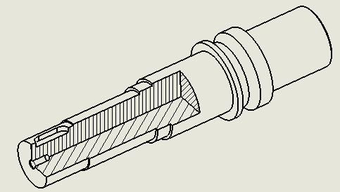
- Now select the threes faces produced by the cut extrude.
- Set the Hatch options and click OK. You may set options for individual face by selecting the face/hatch and accordingly set the hatch options.


Using Broken Out Section View
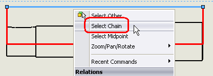
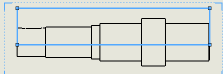
- Place the view and create a rectangle as shown. Make sure it passes through the centre. For easy viewing I have thickened the sketch line and colored it red.
- Right click on any line and select “Select Chain”. Complete rectangle will get selected.
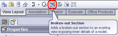
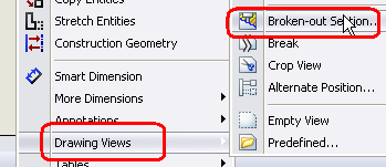
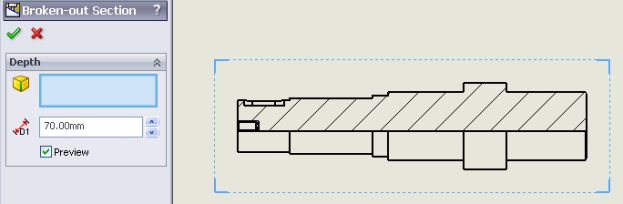
- Click on Broken-out section on View layout toolbar or Insert > Drawing Views > Broken-out section or right-click on sheet > Drawing Views > Broken-out section.
- Specify the depth or select edge etc. to set the depth. You may select the option to see the preview when changing depths.
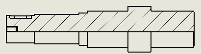
- Click OK after you have set the options.

The above options are shown for parts files only. You can also use them for assemblies.
