Category Archives: Assembly

Mass/Weight in different Units

Michael asked on SolidWorks forums as “How to show weight in Ounces” as this unit is not available under Tools > Document Properties > Units.  If you also looking for similar thing, here is the simple procedure.

  1. Open the part/assembly file or create a new one and add the bodies/parts as required.
  2. No click on Tools > Equation.
  3. Equation Editor will pop up.
  4. Click on Add.
  5. Next you’ll see is “Add Equation” window.
  6. You can also do the above steps by right click on Equation folder and  selecting “Add Equation”.
  7. Write the equation name. I have used “Mass in Oz”
  8. Now type or click on =
  9. Next is expand the equation editor. Click on the two arrow button on the right bottom corner.
  10. Next you’ll see the list of global variables and file properties (with the values)
  11. Click once on SW-Mass (make sure you click only once).
  12. SW-Mass will appear in equation box.
  13. Now type or click on * (for multiplication).
  14. Now add the conversion factor.  As we are converting from grams to Oz, the conversion factor is 1 gram = 0.0352739619 ounces. Depending on the precision, you can change the value. I’ll use 0.0353.
  15. Click on OK to apply the equation.
  16. You can see the evaluated value.
  17. Click OK to exit equation editor.
  18. Now open File properties. Click on Properties under file menu.
  19. You can add the property under Custom/Config Tab.
  20. Add “Weight” as Property name. Set type as “text“. And for value/ text expression, expand the list and select “Mass for Oz“.
  21. Click OK to apply the changes and exit.
  22. Weight will be shown in Oz units (value) where ever linked.
  23. Similarly you can use the method for other conversion works also 🙂

Assembly from Part – No mates required

So far you must have been creating your assemblies from parts using Bottom Up method in which you first design and model parts, then insert them into an assembly and use mates to position the parts. To change the parts, you must edit them individually. These changes are then seen in the assembly OR using Top Down method in which one or more features of a part are defined by something in an assembly, such as a layout sketch or the geometry of another part. The design intent (sizes of features, placement of components in the assembly, proximity to other parts, etc.) comes from the top (the assembly) and moves down (into the parts).

Now take a case of multi body part which you might need as an assembly. The option might be to save the individual body as separate part using “Insert into New part” option, insert them into a new assembly and use mates to position the parts.

STOP using this method and let’s talk of a different and simple method/option called “Create Assembly” which will help us to create an assembly directly from a multi body part without getting into hassles of using Bottom Up method, hence saving a lot of time.

  1. Open or create the multi body part. I have created a steel table with legs and a table top. 
  2. Expand the Cut list or Solid body folder by clicking on the + sign next to Cut list or Solid body folder (As I have weldment part used for describing the method, you’ll see only cut list is being used in next steps)
  3. You will see the bodies contained in the different folder based on their shapes and sizes. Their name is automatically driven through SolidWorks.
  4. Rename (if you wish or need) their name to something meaningful or something you can recognize easily.
  5. Now right click on the cut list and select save bodies.
  6. Next you’ll see Save Bodies property manager. Click on Auto-assign Names.
  7. The names which you have given in step 4 will be applied to the bodies here. Don’t worry about the order of the bodies.
  8. Now comes the important step. Click on Browse under “Create Assembly” in the same Save Bodies property manager. This will prompt you to create/save a new assembly.
  9. Key in the required assembly name and click on save.
  10. Finally click OK under Save Bodies property manager to execute the command of creating the assembly.
  11. Hurray, you have just made an assembly from a multi body part. The new assembly will open up or in case it don’t, you can always open it up from the location where you saved it.
  12. Now you can use this new assembly for other assembly operations like exploded view, BOM, etc.
  13. Also any changes done in the part will be reflected in the assembly. 

Animating a Cylinder Grow

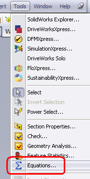
Do you need to show animating cylinder i.e. increasing or decreasing height of a cylinder. Then here is a quick and easy way of doing that. Please note that you can use any unit system (metric or inches) for this tutorial.

1. Start a new part and save it without creating any features or sketch in it. I would call this part as Dummy part.

2. Start a new assembly and save it as Animating Cylinder.

3. Insert the part into this new assembly using Insert Component option (Insert > Component > Existing Part/Assembly)

4. Browse to the part location and drop the part anywhere in the assembly or simply click on OK.

5. If you notice a (f) part name in the assembly in front of manager tree, then right click (RMB) on it and select float from the list. The (f) indicates that part is fixed which means it can make any movement. But as we need to move the part, we need to make it free. Hence we selected float. Now the part can move in any direction.

6. The (-) in front of part name indicates that part is free to move/rotate anywhere.

7. Now select Front planes of the assembly and of the dummy part and add a coincident mate.

8. Select Right planes of the assembly and of the dummy part and add a coincident mate.

9. Add a distance mate of any value (say 10 mm) between the Top planes of the assembly and of the dummy part. You may have to set the position of Top plane of Dummy part as required. Use Flip dimension to set to the position.

10. Start a new part within the assembly (i.e. in context modeling). With the options coming up in new versions, you can save the file internally in the assembly itself. Insert > Component > New part.

11. Click or select Assembly Top plane to start the sketching for new part. You’ll notice a change in the pointer.

12. Now you’ll be the part edit mode and further in the sketching mode. Create a circle with center at the origin and of any diameter.

13. If you feel/require, you can dimension the circle. As a best practice and good habit, it’s always better to use a fully defined sketch. I have given a diameter of 80 mm.

14. Now click on Extrude Boss/Base or Insert > Boss/Base > Extrude.

15. You’ll a see a preview of the extruded cylinder. Click on Direction 1 and then select “Up to Surface” from the drop down list for extrude end condition.

16. Now click in the Face/Plane selection box to define the face/plane for the extrude condition.

17. Expand the feature manager tree by clicking on the plus sign next to assembly name.

18. From the list, select Top plane of the Dummy part.

19. You’ll see the Top plane (Dummy part) in the Face/Plane box of extrude command. Click OK to exit the command.

20. Click on Edit component to exit part editing and move back to assembly editing.

21. This is how the screen will look like.

22. Now switch to Motion Study.

23. Drag the time to any time level/distance. I have set it to 6 sec.

24. Expand the Mate folder by clicking on the plus sign.

25. From the list, double click on Distance mate.

26. You’ll see dimension edit dialog box. Change the value to any value. I have set it to 50mm.

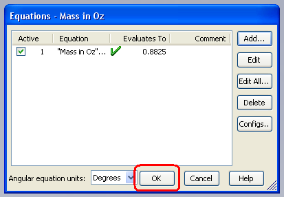
27. Click OK to save the current value and exit the dialog box.

28. You’ll now see the time bar (blue color) in front of Distance mate indicating the change in mate dimension.

29. Click on calculate. And then once calculation is over, you can see the cylinder growing. Use play button to play the animation.

30. You can set Playback mode to Reciprocate to see cylinder increasing and decreasing in size.

Adding Sketch length to Part properties

This is a very simple example on representing sketch length (individual or total length of sketch) in the part properties.

1. Start a new sketch or edit exiting one.

2. Dimension the sketch as required. Make sure you add the chord/arc length to any radius entities (click here to see how to create an arc length dimension) instead of radius value (if required you can set the chord/arc length as driven dimension.

3. Within the sketch mode, start an equation by either right clicking on the equation folder or Tools > Equations

4. You can use any name for this equation (I have used Total length as I’ll creating a total sketch length).

5. Set the equation equal to sum of all the 3 dimensions (can be more or less as per the sketch). You can also set equations for individual dimension.

5a. Add = sign after the equation name

5b. Click on the dimension you want to add. You can select the dimension in any order.

5c. The dimension name will appear in the equation editor.

5d. Add + after the dimension name.

5e. Select the second dimension you want to add, add the + sign and finally select the last dimension. If you more dimensions to add, keep on repeating till you select the last dimension (don’t add any sign after the last dimension name).

5f. Make sure you select the chord/arc length dimension and not radius dimension.

6. Finally click OK on the equation editor (to exit the editor).

7. You can see the finally evaluated vale in the equation manager. The value will be different in your case.

8. Click OK on the equation manger to exit it. And you may also exit the sketch edit mode.

9. Go to file properties.

10. Under custom/configuration tab, add the required name under Property name (I have used Total Length here also as the property name)

11. Select text under type from the drop down list.

12. Finally select the equation (as created in step 3 above) under value/text expression from the drop down list.

13. The final value will appear under evaluated value.

14. Click OK to exit the property manager/summary information.

15. Now you can link your notes to this property.

Do you use a different method? If yes, how about sharing the same.

Thanks

Adding / Removing Jogs

Just a quick presentation on how to Add or Remove a Jog

What is JOG? There can be several answers for this question but if we talk in engineering, the answer might be adding bends to an entity. The entity can be a line (2d sketch or 3d sketch), a note leader or a linear dimension extension line.

Click on the pictures to read in detail on How to Add OR Remove Jogs on specific entities.


Adding Jog to a 3D sketch

1. The process is same as seen for 2d sketch.
2. Start a new sketch or edit an existing one.

3. While in sketch mode, go to Tools > Sketch Tools > Jog

4. Select the line you want to add the jog to.
5. Now with the line selected, drag you pointer up or down or either side and draw the jog as required.
6. You can add relations/dimensions to constrain the jog.

7. To remove the jog, select the entities you to delete and press delete on the keyboard or RMB > Delete.

Adding Jog to a 2D sketch

1. Start a new sketch or edit an existing one.

2. While in sketch mode, go to Tools > Sketch Tools > Jog

3. Select the line you want to add the jog to.

4. Now with the line selected, drag you pointer up or down or either side and draw the jog as required.

5. You can add relations/dimensions to constrain the jog.

6. To remove the jog, select the entities you to delete and press delete on the keyboard or RMB > Delete.

Flexi Tube -1 (motion thorough a tube)

Just another fun with the SolidWorks animation. This one talks more on in-context modeling approach and how to use that for animation. Though more focus will be on creating the animation but yes there is small though most important role of in-context modeling.

Preparing for the animation:

1. To start, create a spherical ball of any dia and the save the part as Ball ( I have taken the dia as 3in).

2. Start a new assembly and save it with any desired name and preferred location.

3. Insert a new part via Insert > Component > New part*.

4. Select front plane as the base plane for new part. You may choose a different plane too.

5. Create a sketch on as shown in the pic (you may choose different values for the dimensions).

6. Using revolve feature, create a cylinder and finally exit the part edit mode. You may save the part internally or externally as desired.

7. Now insert the ball part (created in step 1) into the assembly. Place it any where in the assembly and make sure it is floating i.e. not fixed.

8. Add two coincident mates (between front planes of ball and assembly and similarly between top planes of ball and assembly).

9. Add a 1.6in value distance mate between right planes of ball and assembly.

10. Now switch to part edit mode and edit the long tube/pipe (created through steps 3-6). You can right click on the part in graphics or in the feature manager and select edit part.

11. Start a new sketch on the front plane of the pipe.

12. Expand the feature tree for ball part and select the sketch used to create the ball.

13. Click on convert entities. This will copy the sketch used for ball onto the front plane of the pipe

14. Using horizontal line as centre line, create a revolved feature.

15. Hide ball part for easy selection and further feature addition/editing. Right click on the ball part and select hide components.

16. Add a fillet of 0.25in as shown.

17. Add a shell feature with 0.1in as wall thickness, shell outward and select both the ends of the tube under faces to remove.

18. Create another sketch on the front plane of the pipe (as shown) and do a revolve cut.

19. Exit part edit mode. And finally save the assembly.

You have finished with doing the required steps prior to animation.

* If you are using SW2007, then you’ll have to save the part externally but in higher versions, you can save the part internally in the assembly. Check SolidWorks help for more details on it.

Creating the animation:

1. Switch to motion manger/study. Set the view orientation as required.

2. Drag the timebar to any time value (I have set it to 10 seconds).

3. Now double click on the distance mate mate. This will highlight the distance value and dimension modify window will pop up.

4. Key the desired value (I have used 13.5in) and click OK to finish distance modifications.

5. Now hit calculate and then finally you can play/save your animation. Check the video under My Videos section.

Enjoy playing motion with different shapes/sizes.

Creating New View Orientation

While working on parts/assemblies, sometimes you need a view different other than the standard views for a quick presentation. You set your view, take the snapshot or save as jpg for the moment. But next time when you need the same view orientation, it may take several trials and error to get closer to what you did last time. The simple solution is to save you view orientation.  The procedure is also simple and you can save multiple numbers of view orientations. Apart from presentations, you can also use these customized view orientation in drawings also.

Creating the New View Orientation:

1. Set the view orientation as required.

2. Hit Spacebar to get the View Orientation window.

3. Click on New View (add new view).

4. In the Named View window, enter a desired view name.

5. Click OK on the Named View window. You can see the new view orientation in the view list. Finally close the View Orientation.

6. To access the new view orientation, either hit spacebar and double click on the view orientation name or select it from the heads up toolbar from the views.

Creating the New View Orientation (Sectional View):

You can use the above method to create named view orientation for sectional view to quick access to sectional views which you might be creating often while working on projects. This will save item in getting back to that particular sectional view.

1. Set the sectional view orientation as required.

2. Repeat Steps 2-5 as described above for creating the new sectional view orientation.

Deleting the New View Orientation:

To remove/delete a named view orientation (created using methods described above), simply bring up the list by pressing spacebar, select the named view orientation you want to delete and press delete key on the keyboard.

Motion along Path

As the name suggest, the post talk about creating a quick animation of part(s) along a path. The path can be open or close. And to illustrate the method, I have used very simple parts (a box and a path).

Preparing for the animation:

  1. To start, create a rectangular box of any size.
  2. For the path, you can create a new part with the path (basically a sketch) or start a new assembly, start a new part and create the path or simply create the path sketch at assembly level ( I have used the path created at assembly level by creating new part).
  3. Insert the box into the assembly containing the path (sketch). Make sure you have set the box to float in case if it is fixed by default.
  4. Position your box by applying the suitable mates. I have used one coincident mate to freeze some of the degrees of motion/freedom.
  5. Now define a path mate. Start Mate manager and under Advanced Mates, select Path Mate.
  6. For Component Vertex, select the part vertex to attach to the path (you can select any vertex as per the condition or your part placement).
  7. For Path Selection, click on selection manger. (If you have converted the path to a single spline then you just select the sketch for defining path without using the selection manager option).
  8. Switch to Select closed loop option in the selection manager.
  9. Now select the sketch defined for path (the whole sketch will get highlighted).
  10. Click OK to define the path.
  11. Under Path Constraint, select Distance along Path and set the value to 0. Keep rest of the settings unchanged.
  12. You may select/uncheck Flip dimension to change the direction.
  13. Finally click OK to define the mate and exit mate manager.
  14. Tip: Measure the full length of the path (using measure tool to define the distance value). You may also convert the path into single spline (using fit spline option). This facilitates easy selection without using the selection manager in defining path.

You have finished with doing the required steps prior to animation.

Creating the animation:

  1. Save your assembly (any location and name as desired) and switch to motion manger/study. Set the view orientation as required.
  2. Drag the timeline any time value.
  3. Now double click on the path mate. This will highlight the distance value and dimension modify window will pop up.
  4. Key the desired value and click OK to finish distance modifications.
  5. Now hit calculate and then finally you can play/save you animation.

Tip: You can hide the path if desired.

Here is the link to video: Path Mate

Enjoy playing with motion along different paths.