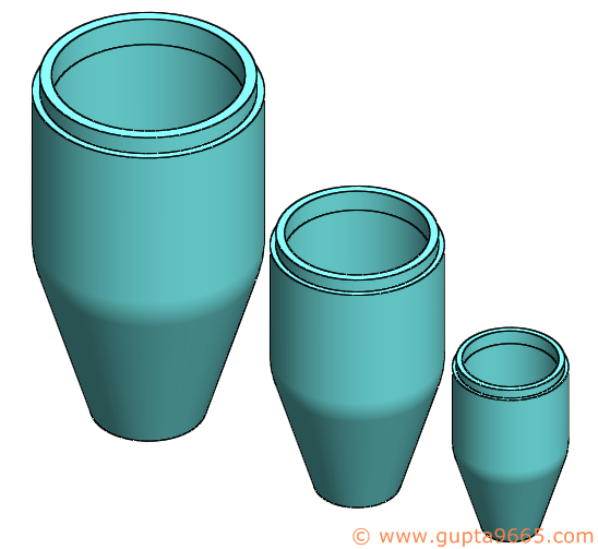
We all use Scale feature in the model to quickly scale up or down a model. The idea is to quickly change the geometry of the model for various purpose. For e.g. in a plastic mold, components are usually scaled up to take care of shrinkage. The scale value depends on the plastic material. It does not scale dimensions, sketches, or reference geometry but only the model geometry (body). One can scale a solid or surface body about its centroid, the model origin, or a coordinate system depending on the requirements.
Applying a Scale:
1. Open the model you want to apply scale to.
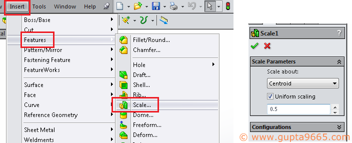
2. Go to Insert > Feature > Scale OR use Scale icon from the toolbar.

3. Select the required option from the drop down for “scale about”
4. Fill in the required value and click OK.
5. Scale feature is added to the model.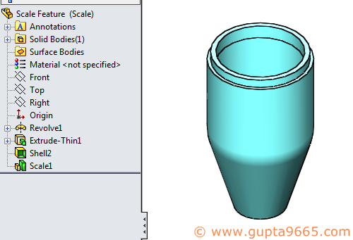
You can scale selected bodies in case of a multi body part.


You can also scale with different values of X, Y and Z directions by deselecting uniform scaling and adding required values for X, Y and Z directions.

Now if you have various configurations, you can easily control the scale factor value for them using two simple methods.
Method 1: Scale Property Manager (might not work for older versions than 2014)
1. Open the Model having the configurations
2. Go to Insert > Feature > Scale OR use Scale icon from the toolbar.
3. Select from the drop down for “scale about”
4. Choose uniform scale or uncheck it.
5. Key in the desired scale value.
6. If you have more than one configuration in the model, then you would see another box for the configuration selection. Select the desired option and configuration accordingly.

7. Click OK and Scale feature is added to the model.
Method 2: Design Table
1. Open the Model having the configurations.
2. Insert a design table (Insert > Tables > Design Table) OR edit the existing design table
3. If you already have a scale feature then it should get added to the design table. If not then add the column headers for controlling the scale feature.
4. In case you want to keep the uniform scale, add column header as $X_AXIS@Scale Feature Name and desired value for each config.
5. In case you want different values for X, Y and Z directions, then add three column headers as $X_AXIS@Scale Feature Name, $Y_AXIS@Scale Feature Name, $Z_AXIS@Scale Feature Name and desired value for each config.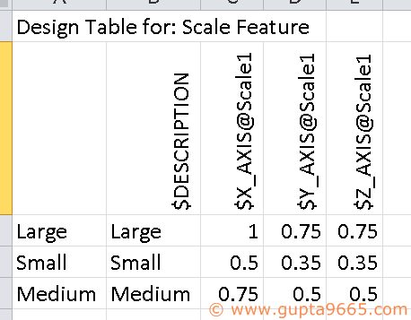
6. Exist the design table and your scale feature in now controlled via design table.


