Category Archives: Drawing

Alternate Position or Configuration in SolidWorks

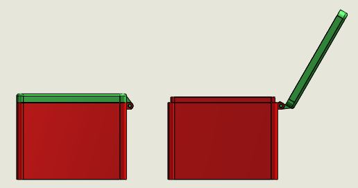
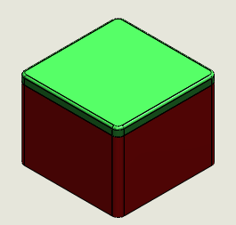
Do you ever need to show open/closed positions or parts movements in drawing views. Let’s take an example of Box Cover Assembly to explore two different ways of presenting the required views.

Alternate Position View Method:

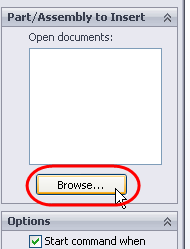
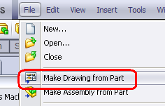
1. Start a drawing and place the assembly view as required.

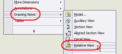
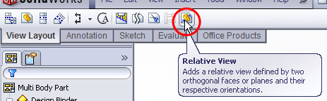
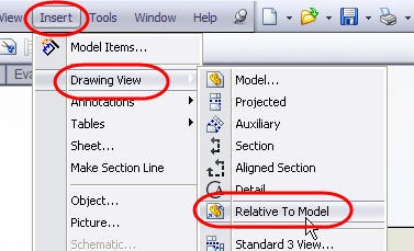
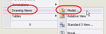
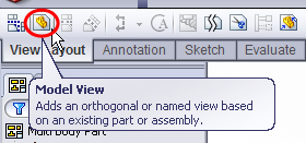
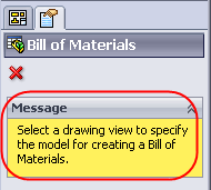
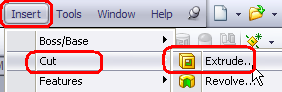
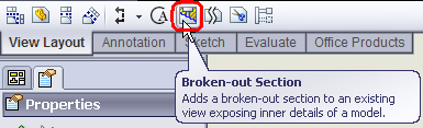
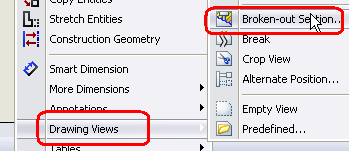
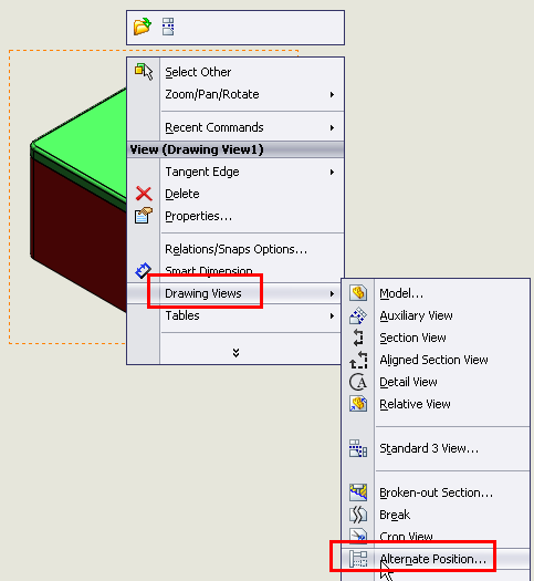
2. Right click on view and select Drawing View > Alternate Position View or go to View layout and click on Alternate Position View. You’ll be prompted to select a view if not selected.

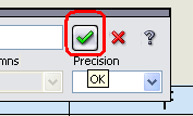
3. Alternate Position View will generate a new configuration in the assembly. So give the desired configuration name and click OK.

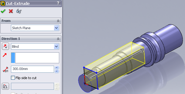
4. The mode will change to assembly from drawing.

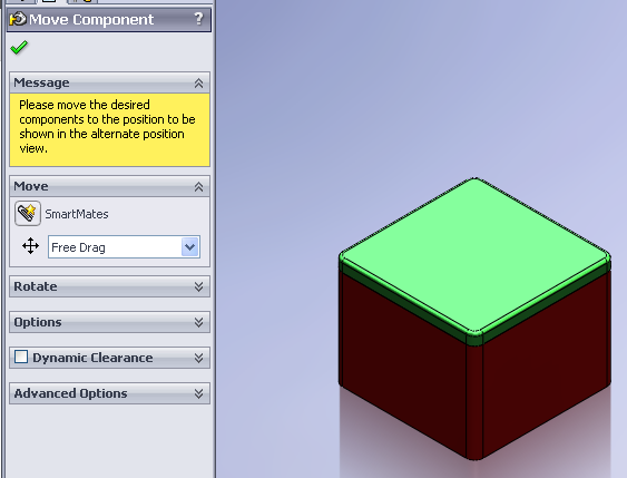
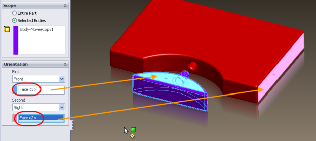
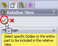
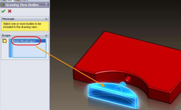
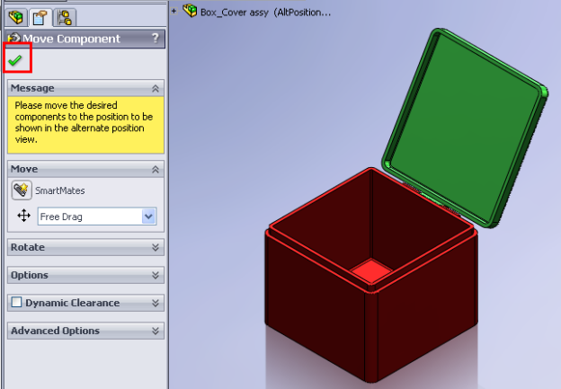
5. Set the part(s) in desired position and click OK. (P.S. There has to some parts in the assembly that are not completely fixed else you won’t be able to drag/move them to new position).

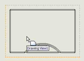
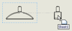
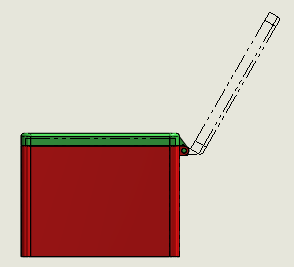
6.  The drawing will get updated with Alternate Position View shown in dotted in the same view.

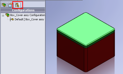
Configuration Method:

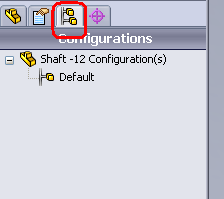
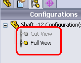
1. Open up the assembly and switch to configuration mode.

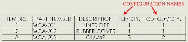
2. Add a new configuration named Opened (or you may give  a different name too).

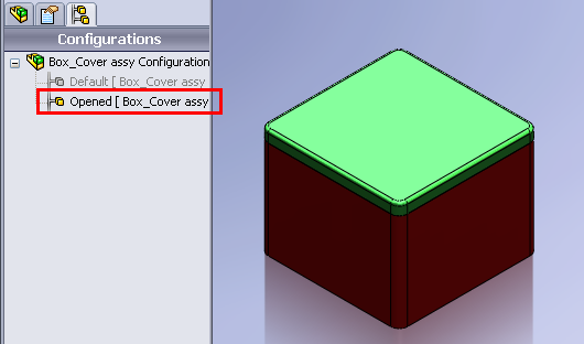
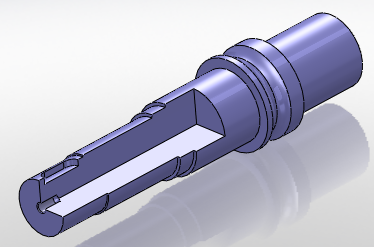
3. Set the part(s) in desired position (by editing mates) so that both configuration have different part(s) position(s).

4. Save assembly and start a new drawing.

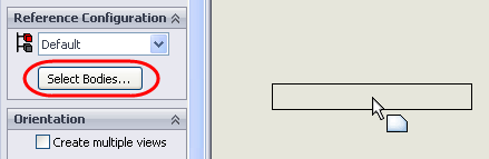
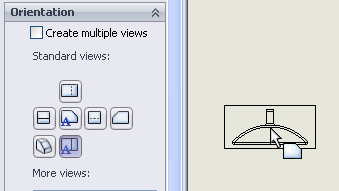
5. Place the desired view.

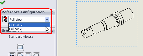
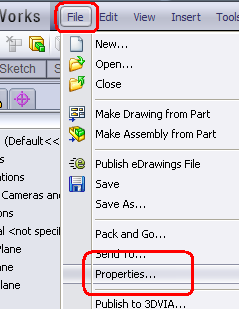
6. Right click on drawing view and select properties.

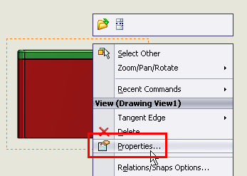
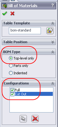
7. In the Drawing View Properties dialog box, under Configuration information,  select Use named configuration and select the Opened configuration from the list. Click OK.

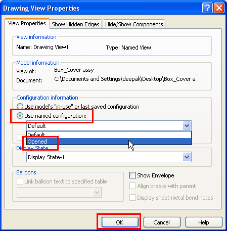
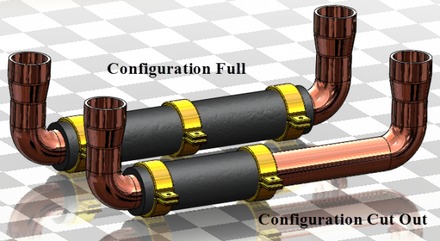
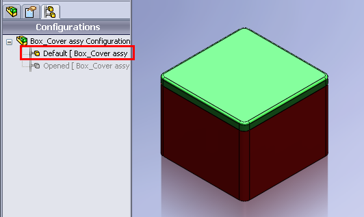
8. The view configuration will change to Opened configuration and part(s) position(s) will get updated as per configuration.

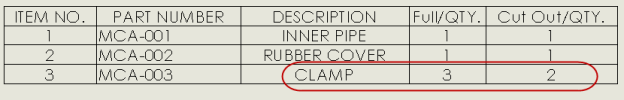
9. If required you may show two different views showing open and closed positions.

Detailing a Multibody Part -1


Multibody Part. A part with separate bodies within the same part document

The tittle speaks up everything and I see many time people asking for it.  So here you go.

There can be several ways to detail out a multi body part.

Relative View method:

  1. Start a drawing and inert a view.
  2. Right click on the view and select Drawing Views > Relative View or click Relative View on the View toolbar or Insert > Drawing Views > Relative to Model.
  3. Make sure you have selected the view or you’ll be prompted to select a planar face of the model. To select, simple click on the view.
  4. The part will open up with Relative View property manager.
  5. Click on “Selected Bodies” and select the appropriate body you want to detail out.
  6. Select faces for Font and Right sides if you want to orient the views in different ways.
  7. Click OK to exit Relative View property manager and switch back to drawing mode.
  8. Place your view and any further views as required.
  9. Dimensions as required.

Assembly method:

Convert the multi body part to an assembly, then detail them as single part. Here is quick way to convert them in an assembly.Assembly from Part – No mates required

Reference Configuration and Bodies method:

  1. Start a new drawing.
  2. Right click on the sheet and select Drawing Views > Model View or click Model View on the View toolbar or Insert > Drawing Views > Model View.
  3. Click on browse and select the multi body part.
  4. You’ll be prompted to place the view but don’t click anywhere on the sheet. Click on “Select bodies” under Reference configuration. You mat change the configuration in case you have multiple configuration in that part.
  5. The part will open up with “Drawing View Bodies” property manager.
  6. Select the appropriate body you want to detail out.
  7. Click OK to exit Drawing View Bodies property manager and switch back to drawing mode.
  8. Select the view orientation as required.
  9. Place your view and any further views as required.
  10. Dimensions as required.

Multi Configuration in Assy BOM

Do you know you can show multiple configuration in single BOM. Check the steps to know how to do it in case you need it.

The assembly I have used here has two configurations, named Full and Cut Out. The difference is the number of clamp part plus cutout in one of the configuration.

  1. Insert the drawing view as required.
  2. Insert BOM table by right clicking on the View, selecting Tables > BOM OR select the inserted view and then go to Insert > Tables > BOM
  3. If you don’t have a view selected, you’ll be prompted with a message to select a view.
  4. You can select the view by clicking on it.
  5. Now BOM property manager will appear. Under BOM Type select “Top Level only” and under Configurations, select all the configurations or the required one. I have selected all in the list i.e Full and Cut Out.
  6. After setting up the options, click on OK.
  7. Place you BOM as required OR if you have a fixed anchor, you can set the BOM to attach to anchor under table position in BOM property manager. Check the quantity of desired parts. In this case it was the Clamp part whose quantity is correct as required.

Playing with Drawing Views

Let’s play with drawing views and make them jump from sheet to sheet 😉

Look at the picture below. There are three views on Sheet 1. The game is to move the Detail view A to Sheet 2.

Rules: Use any method but not create a new view.

Let’s start the game.

Method 1

  1. Activate the Sheet 1 (or the sheet from which you want to move the view to other). You do it by clicking on the respective sheet in the sheet tab or right click on sheet and select Activate.
  2. Select the Detail view A in feature manager tree.
  3. Now drag and drop the view to Sheet 2 (or to the sheet where you want to move your view). Make sure you drag it just under the sheet name in feature manager tree as you can place it at other location. You can notice the change in cursor icon in both conditions.
  4. The view is on Sheet 2.
  5. You can see it by activating the Sheet 2 or looking at the feature manager tree.

Method 2

  1. Activate the Sheet 1 as stated in step 1 above.
  2. Select the Detail view A in feature manager tree or in the drawing sheet.
  3. Press Ctrl + X (on keyboard) or Edit > Cut.
  4. You’ll be prompted with a message to confirm Deleting the view. Click on Yes
  5. Now activate the Sheet 2 using method stated above and click anywhere on the sheet.
  6. Press Ctrl + V (on keyboard) or Edit > Paste or Right click on the sheet and select Paste.
  7. The view is on Sheet 2.

Mission accomplished 🙂

Different ways to create Half Section in Drawings

Do you ever need to show HALF Section views in the drawings??

Let’s discuss various ways to create them.

Using Section View

  1. Start a new drawing and insert a view.
  2. Activate the view and insert an L shaped sketch. Using SW auto snap options start the sketch in line with the circle/arc quadrant or centre point.
  3. Click on the line and select section view on view tool bar or Insert > Drawing Views > Section or right-click on sheet > Drawing Views > Section.
  4. Click NO on the prompt window for partial section.
  5. Place the section view on appropriate location.
  6. Now right-click on section view and select Isometric Section View.
  7. You may remove the section view label if required.
  8.  

    Using Configuration

  1. Open the part for which you want to create the half section.
  2. Start a new sketch on the face/plane.
  3. Create a rectangular as shown.
  4. Click on Extrude cut on feature tool bar or Insert > Cut > Extrude. You may or may not exit the sketch editor.
  5. Using any options, create the cut extrude feature.
  6. Switch to configuration manager.
  7. Add a new configuration. I have added a Cut View named configuration. And renamed the other to Full View. You can give any name as desired/required.
  8. Activate the full view configuration and switch back to feature manager. Suppress the cut extrude feature we added above.
  9. Now we have Full View and Cut View configuration with no cut and cut.
  10. Start a new drawing and place a view. Set the configuration to Cut View in case you don’t see the cut.
  11. Click on Area Hatch/Fill on Annotation toolbar or Insert > Annotations > Area Hatch/Fill or right-click on sheet > Annotations > Area Hatch/Fill
  12. Now select the threes faces produced by the cut extrude.
  13. Set the Hatch options and click OK. You may set options for individual face by selecting the face/hatch and accordingly set the hatch options.

Using Broken Out Section View

  1. Place the view and create a rectangle as shown. Make sure it passes through the centre. For easy viewing I have thickened the sketch line and colored it red.
  2. Right click on any line and select “Select Chain”. Complete rectangle will get selected.
  3. Click on Broken-out section on View layout toolbar or Insert > Drawing Views > Broken-out section or right-click on sheet > Drawing Views > Broken-out section.
  4. Specify the depth or select edge etc. to set the depth. You may select the option to see the preview when changing depths.
  5. Click OK after you have set the options.

The above options are shown for parts files only. You can also use them for assemblies.

Hide or Show Annotations (Dimensions, Symbols)

As the tittle name says Hide or Show, we will become a magician in SolidWorks drawing and hide or show Annotations (Dimensions, Symbols). There might be requirements sometime while working in drawing to hide or show Annotations. One quick way is to delete unwanted Annotations (Dimensions, Symbols) (by selecting them and press delete) and insert them back when required (using model items). But this method might be tedious sometimes and also you may forgot as which one was unwanted and which was required on the drawing. Similar to Mitchell requirements on Solidworks forums.

OK let’s take a simple example to understand what easy process can be used.

  1. Start a new drawing and insert view(s).
  2. Insert Dimensions.
  3. Insert any symbols (if required).
  4. Click on Hide/Show Annotations under View. All annotations are displayed; even if there are any hidden annotations, they’ll show up in gray. If you want to observe this repeat these steps after hiding some annotations, dimensions.
  5. The pointer changes to
  6. Click on the dimension, symbols, etc. you want to hide. After you select them they’ll change to gray color.
  7. After you’re done with the selection, right click any where on sheet and click on “Select” or simply press ESC (on keyboard).
  8. Other method is to right click on the annotation and select Hide. You may multi select annotations and them hide them all together.
  9. BINGO, the selected annotations have disappeared.
  10. OK, now let’s show them back.
  11. Again click on Hide/Show Annotations under View or right click any where on sheet and select Hide/Show Annotations under Recent commands.
  12. The hidden annotation will appear (in gray color).
  13. Now select the one you want to show back.
  14. After you’re done with the selection, right click any where on sheet and click on “Select” or simply press ESC (on keyboard).

Wow you have become a SW magician now 😉

Mass/Weight in different Units

Michael asked on SolidWorks forums as “How to show weight in Ounces” as this unit is not available under Tools > Document Properties > Units.  If you also looking for similar thing, here is the simple procedure.

  1. Open the part/assembly file or create a new one and add the bodies/parts as required.
  2. No click on Tools > Equation.
  3. Equation Editor will pop up.
  4. Click on Add.
  5. Next you’ll see is “Add Equation” window.
  6. You can also do the above steps by right click on Equation folder and  selecting “Add Equation”.
  7. Write the equation name. I have used “Mass in Oz”
  8. Now type or click on =
  9. Next is expand the equation editor. Click on the two arrow button on the right bottom corner.
  10. Next you’ll see the list of global variables and file properties (with the values)
  11. Click once on SW-Mass (make sure you click only once).
  12. SW-Mass will appear in equation box.
  13. Now type or click on * (for multiplication).
  14. Now add the conversion factor.  As we are converting from grams to Oz, the conversion factor is 1 gram = 0.0352739619 ounces. Depending on the precision, you can change the value. I’ll use 0.0353.
  15. Click on OK to apply the equation.
  16. You can see the evaluated value.
  17. Click OK to exit equation editor.
  18. Now open File properties. Click on Properties under file menu.
  19. You can add the property under Custom/Config Tab.
  20. Add “Weight” as Property name. Set type as “text“. And for value/ text expression, expand the list and select “Mass for Oz“.
  21. Click OK to apply the changes and exit.
  22. Weight will be shown in Oz units (value) where ever linked.
  23. Similarly you can use the method for other conversion works also 🙂

How to use Equations in Drawing Tables

Do you have situation where you need equation to represent total weight, total length or something similar. I do sometimes need that. But now the question arises as how to do that. Where to put the equations to get the desired result. Let’s take a simple example of 4 welded pipe to explain the process.

The part contains a pipe of 2 different lengths welded corner to corner. The cut list shows the two different lengths and weight of one pipe each which means it is displaying the weight of just one pipe and not two pipe. Now someone on the manufacturing floor needs the combined weight of 2 pipes of same length. So we need to show the total weight of two pairs of pipe.

The weight displayed are 47.80 gms and 63.73 gms. But this is weight for one single pipe of each length and not the total weight. One way might had been to multiple the weight property in the cutlist (in part) by the quantity and get the desired result. Let’s try that.

  1. Open the part
  2. Expand the cut-list folder and right click on any of the cut-list item. Select Properties.
  3. Multiple the weight value by quantity i.e. by 2.
  4. The result is not what we need.

But this doesn’t mean it can be done. There are SW API experts who may be able to make a quick macro or script to do it. I’m not an expert with API so that is not in my scope.  Now the question is “Is there an easy way to do it”? The answer is Yes. Let’s see how to do it in an easy way.

  1. Start a new drawing.
  2. Add the required views. (I haven’t displayed the complete drawing but just an Isometric view)
  3. Add the cut-list. The cut-list format might be different on your machine. The cut-list here displays length and weight for one pipe but quantity displayed is two ech.
  4. Right click on the weight column. Select Insert > Column Right. This will add a new column on the right side.
  5. Hover your mouse on the top of new column and you’ll see a cyan box with some alphabet (F in this case).
  6. Click on the cyan box and you’ll see the column property manager.
  7. Keep the “User defined” selected under column properties and under tittle write TOTAL WEIGHT. You may write another tittle too. Click OK to set the tittle.
  8. Now click on cell next to weight value (in the first row). You’ll see the cell formatting window.
  9. Click on equation icon.
  10. Table Equation Editor will pop up.
  11. Now click on the column cell which you want to include in the equation.  Quantity cell (B2) in this case.
  12. Now type * (for multiplication).
  13. Now click on the Weight cell (E2) to include it in the equation (because we need total weight).
  14. The equation is complete now and will look like B2 * E2. You might have different cell number base don your cut list table.
  15. Finally click on OK to set the equation.
  16. The final value will appear in the required cell under Total Weight Column.
  17. Repeat the process for the bottom cell  or copy paste the equation from F2 to F3 but you’ll have to edit the cell number to get the correct value.

Similarly you can use the method for other drawing tables also.

Hole Table Precision

Looking for setting decimal precision in a hole table to get more accuracy i.e. you have a table like this (below)

but need like this (below), means you looking for precision in decimal places.

1. Open the drawing.
2. Go to Tools > Options > Document Properties > Tables.

3. Expand Tables and click on Hole.

4. Set the Trailing zeros to Show.

5. Click OK (to apply the settings and close the Document Properties).
6. Trailing zeros are displayed according to the decimal places you specify for Units under Tools > Options > Document Properties

Zippy now you can ask for more accurate hole location from the shop floor 😉 and similarly you can set dimension precision for BOM and General tables.

Rotating a Drawing View

Sometimes one need to show a rotated view in the drawing. If is available in the standard view, once can simply place it as desired. If there is no view as required, one may go to part or assembly and create a new view orientation and then use that in the drawing. To avoid that one can simply rotate the drawing view as required.

1. Click on the view or select the view you want to rotate.

2. Click on Rotate View on the heads up tool bar or standard tool bar.

3. You’ll now see a Rotate Drawing View pop up window.

4. Fill in the desired angle value (I have used 90°). You can also key in a negative value.

5. Once you have keyed in the desired value, click on Apply and view will be rotated.

6. Then click on close to exit the command and you’ll have a rotated view.