Category Archives: Assembly

Animating Geneva Mechanism in SolidWorks

I’have been seeing lot of people talking on Geneva Mechanism over various forums and even I have been wondering myself on animating a Geneva Mechanism in SolidWorks. In the past I had used many different tricks to achieve it like gear mates or using surfaces etc.

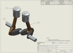
Here is an animated view of what I have done few days back. I have been modelling some simple file to put up for this post but I recently came across SolidWorks Geneva-Device files on GrabCAD by Bobby Dyer. I would like to thank him for allowing me to use his files to create this tutorial.

Based on the requirements Geneva Mechanism can be external or Internal:


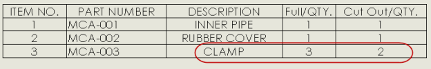
You can download the files used for this tutorial here: SolidWorks Geneva-Device files.  The important ingredient are Contact and Motion Study Properties

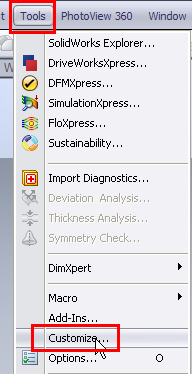
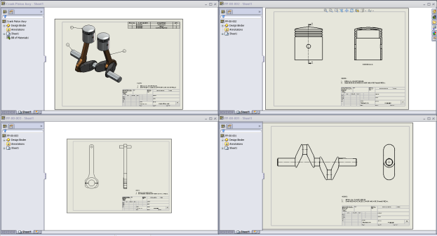
1. Open the “Geneva Device” assembly from the downloaded files.

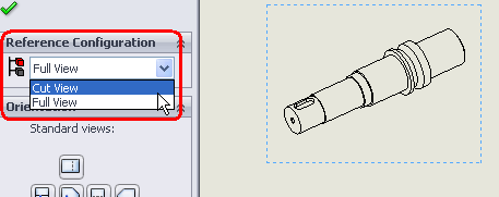
2. Switch to Motion study and set the model orientation as required.

3. Change the Motion study type to “Basic Animation“.

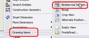
4. Click on “Contact“.

5. Now in the Contact property manager click on the pin to keep it visible as we need to use it twice.

6. Now under components selection box, select “Index Wheel” and “Advance stop” parts.

7. You can select them from graphic area OR from feature manager tree OR motion study tree.

8. Click OK to apply the contact.

9. With Contact property manager visible, select “Index Wheel” and “Indexer” parts and click OK to apply the contact. You can now close the Contact property manager.

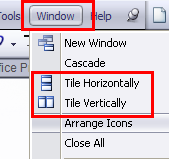
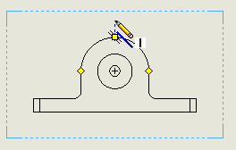
10. Click on “Motor“.

11. Set the motor type to “Rotary motor“. Select the cylindrical face or circular edge of “Index Wheel” or “Indexer” parts to define the direction of ( I have selected the cylindrical face of the Indexer). Set the motion function to “Constant Speed” and RPM to 30.

12. Click OK and apply the motor.

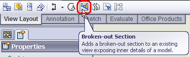
13. Now click on “Motion Study Properties“.

14. In the Motion Study Properties property manager under basic motion, set the frames per second to 30 (the larger number the more smoother motion) and set the Geometry Accuracy and 3D Contact Resolution settings to high side (move the sliders to right). This will make collision simulation more accurate and smoother motion, but requires more time to compute.

15. Click OK to set the properties.

16. Finally click on “Calculate“.

17. And now is the show time. Hit play to enjoy the show.

You can change and experiments with the settings to get a better animation. Click on save if you want to export the animation as AVI or series of pictures. You can change other settings in the save window.

Making your Drawing Sheets Party together

Do you ever move your sheets from one drawing to another or combine several drawings into one. Let’s play a game to move sheet from one drawing and make it party with other drawing.

You can download the files from here.

1. Open all the drawing files.

2. You may arrange them  (by clicking on Windows menu and setting Vertically or Horizontally)  so that you can select quickly.

3. Now activate the drawing from which you want to copy the sheet.Right click on the sheet in the sheet tab or in feature manager and select COPY.

4. Now activate the drawing in which you want to copy the sheet. Right click on the sheet in the sheet tab or in feature manager and select PASTE.

5. Set the position as required.

6. You can see the sheet copied over to the selected position.

7. Similarly you can do for other sheets if required.

8. You may rename the sheets. Right click on the sheet in the sheet tab, select rename and set the new name OR right click on the sheet in feature manager and select Properties OR right click anywhere on the sheet and select properties. In the pop window, set the new name.

Changing Context Toolbar options in SolidWorks

Context Toolbars

The context toolbar started their career with SolidWorks 2008 version. When you select items in the graphics area or Feature Manager design tree, context toolbars appear and provide access to frequently performed actions for that context. The tools in the context toolbar are a subset of items previously found on the shortcut menus.

(above pictures taken from SolidWorks online Help files)

I’m liking the feature from it debut entry and many more like me love it.  And if you’re one of those who are getting used to it, you can change the setting to get the older behavior of menus in the drop down list.

To set it up

1. Open a part, assembly, or drawing document.

2. Click Tools > Customize, OR right-click on any toolbar and select Customize OR right-click at the top or bottom of the window and select Customize OR click Options > Customize.


3. On the Toolbars tab, uncheck  Show in shortcut menu under the Context toolbar settings.

4. Click OK and enjoy the old settings/options.

Different Mate Values for Different Configurations

Do you ever need to set up different mates vales (Distance and Angle mates) for different configurations in the Assembly.

You can download the files used from here to do this exercise/tutorial.

1. Open the Assembly the switch to configuration manager.

2. Add the configuration as required. I already have two configurations in the assembly: Closed and Open.

3. Activate the configuration named Open.

4. Expand the mates folder.

5. Double click on Angle1 mate (so that the dimension displays up in the graphics area).

6. Double click on the dimension.

7. Set the value to 120 and set the option “This Configuration

8. Click OK to set the value and exit the dimension edit box.

9. Rebuild if required.

10 Switch to configuration manager and check both the configurations.

Similarly you can set different values for distance mate too in your assemblies.

Making your Drawing Tables Jump in SolidWorks

This particular topic comes often in various SolidWorks forums that “Can the Tables be moved to another sheets in a Drawing“. The answer is simply Yes and there are various ways to move them to different sheet.

Let’s check the various tables used in SolidWorks first:

In this post, I will be trying to discuss various ways using which one can move these tables to different sheet in a drawing.  You can use any of the methods below to move the table onto other sheet. I have used BOM table to explain these methods and some of the methods explained below might not work on all types of tables.

Cut and paste Method

1. Click on the table you want to move (in the drawing area).

2. Press Ctrl + X (cut) on the keyboard or Edit > Cut.

3. Activate the sheet you want to move the table onto by right clicking on it in the manager tree and select Activate or click on it in the sheet tab.

4. Press Ctrl + V (paste) on the keyboard or Edit > Paste.

5. Your table is now on new sheet, you can set its position as required.

Drag Table Method-1

1. Select the table you want to move from manager tree by clicking on it.

2. With the table selected, keep the left mouse button pressed and drag the table below the sheet name on which you want to move the table onto.  Pay attention to change in pointer when you do that.

3. Your table is now on new sheet, you can set its position as required.

Drag Table Method-2

1. Click on the table you want to move (in the drawing area).

2. With the table selected, take your pointer to the cross (refer picture).

3. Keep the left mouse button pressed and drag the table on the sheet name (in the sheet tab area) on which you want to move the table onto.  Pay attention to change in pointer when you do that.

4. Your table is now on new sheet, you can set its position as required.

Alternate Position or Configuration in SolidWorks

Do you ever need to show open/closed positions or parts movements in drawing views. Let’s take an example of Box Cover Assembly to explore two different ways of presenting the required views.

Alternate Position View Method:

1. Start a drawing and place the assembly view as required.

2. Right click on view and select Drawing View > Alternate Position View or go to View layout and click on Alternate Position View. You’ll be prompted to select a view if not selected.

3. Alternate Position View will generate a new configuration in the assembly. So give the desired configuration name and click OK.

4. The mode will change to assembly from drawing.

5. Set the part(s) in desired position and click OK. (P.S. There has to some parts in the assembly that are not completely fixed else you won’t be able to drag/move them to new position).

6.  The drawing will get updated with Alternate Position View shown in dotted in the same view.

Configuration Method:

1. Open up the assembly and switch to configuration mode.

2. Add a new configuration named Opened (or you may give  a different name too).

3. Set the part(s) in desired position (by editing mates) so that both configuration have different part(s) position(s).

4. Save assembly and start a new drawing.

5. Place the desired view.

6. Right click on drawing view and select properties.

7. In the Drawing View Properties dialog box, under Configuration information,  select Use named configuration and select the Opened configuration from the list. Click OK.

8. The view configuration will change to Opened configuration and part(s) position(s) will get updated as per configuration.

9. If required you may show two different views showing open and closed positions.

Manipulating an Exploded View in SolidWorks

Do you ever need to reorder exploded view steps or feel like renaming them for better understanding/explanation, then check these simple steps:

Preconditions: An open assembly with some parts and preferably with an exploded view.

I’m using an assembly having an exploded view. Check SolidWorks help file on “How to create an exploded view”

To reorder Exploded View steps:

  1. Switch to configuration manger.
  2. Expand the configuration containing the exploded view and edit the feature.
  3. Select the step you want to reposition/reorder.
  4. Drag and drop it on the location you need.
  5. The step in now on the new position. You can close the exploded view property manager and play the changed exploded view animation.

To rename Exploded View steps:

  1. Expand the exploded view and edit the feature.
  2. Select the step you want to rename.
  3. Press F2 on the keyboard.
  4. Rename as required.
  5. Click anywhere and your exploded view step has a new name.

Multi Configuration in Assy BOM

Do you know you can show multiple configuration in single BOM. Check the steps to know how to do it in case you need it.

The assembly I have used here has two configurations, named Full and Cut Out. The difference is the number of clamp part plus cutout in one of the configuration.

  1. Insert the drawing view as required.
  2. Insert BOM table by right clicking on the View, selecting Tables > BOM OR select the inserted view and then go to Insert > Tables > BOM
  3. If you don’t have a view selected, you’ll be prompted with a message to select a view.
  4. You can select the view by clicking on it.
  5. Now BOM property manager will appear. Under BOM Type select “Top Level only” and under Configurations, select all the configurations or the required one. I have selected all in the list i.e Full and Cut Out.
  6. After setting up the options, click on OK.
  7. Place you BOM as required OR if you have a fixed anchor, you can set the BOM to attach to anchor under table position in BOM property manager. Check the quantity of desired parts. In this case it was the Clamp part whose quantity is correct as required.

Different ways to create Half Section in Drawings

Do you ever need to show HALF Section views in the drawings??

Let’s discuss various ways to create them.

Using Section View

  1. Start a new drawing and insert a view.
  2. Activate the view and insert an L shaped sketch. Using SW auto snap options start the sketch in line with the circle/arc quadrant or centre point.
  3. Click on the line and select section view on view tool bar or Insert > Drawing Views > Section or right-click on sheet > Drawing Views > Section.
  4. Click NO on the prompt window for partial section.
  5. Place the section view on appropriate location.
  6. Now right-click on section view and select Isometric Section View.
  7. You may remove the section view label if required.
  8.  

    Using Configuration

  1. Open the part for which you want to create the half section.
  2. Start a new sketch on the face/plane.
  3. Create a rectangular as shown.
  4. Click on Extrude cut on feature tool bar or Insert > Cut > Extrude. You may or may not exit the sketch editor.
  5. Using any options, create the cut extrude feature.
  6. Switch to configuration manager.
  7. Add a new configuration. I have added a Cut View named configuration. And renamed the other to Full View. You can give any name as desired/required.
  8. Activate the full view configuration and switch back to feature manager. Suppress the cut extrude feature we added above.
  9. Now we have Full View and Cut View configuration with no cut and cut.
  10. Start a new drawing and place a view. Set the configuration to Cut View in case you don’t see the cut.
  11. Click on Area Hatch/Fill on Annotation toolbar or Insert > Annotations > Area Hatch/Fill or right-click on sheet > Annotations > Area Hatch/Fill
  12. Now select the threes faces produced by the cut extrude.
  13. Set the Hatch options and click OK. You may set options for individual face by selecting the face/hatch and accordingly set the hatch options.

Using Broken Out Section View

  1. Place the view and create a rectangle as shown. Make sure it passes through the centre. For easy viewing I have thickened the sketch line and colored it red.
  2. Right click on any line and select “Select Chain”. Complete rectangle will get selected.
  3. Click on Broken-out section on View layout toolbar or Insert > Drawing Views > Broken-out section or right-click on sheet > Drawing Views > Broken-out section.
  4. Specify the depth or select edge etc. to set the depth. You may select the option to see the preview when changing depths.
  5. Click OK after you have set the options.

The above options are shown for parts files only. You can also use them for assemblies.

UP-Down through the Feature Tree

Many of us sometimes needs to see that how a model has been built up in SolidWorks. The most commonly used method is to move scroll bar up in the feature manager tree and then move it step by step down. Using mouse for this process can be tedious sometimes.

STOP here. If you also use this method and looking for something easier, then continue reading and learn anew method.

  1. Start SolidWorks and go to Tools > Options or click on Options.
  2. Click on Feature Manager under System Options.
  3. Select (check) “Arrow Key navigation“.
  4. Click OK to apply and close the system options.
  5. Roll back the feature manager tree.
  6. Click on the scroll bar.
  7. Using Up-Down arrow keys, you can now move the scroll bar up or down as required.

Other funtions you can achieve with arrow keys

To …                                                              Press:

scroll up                                                       up arrow

scroll down                                                  down arrow

collapse the design tree                               left arrow with pointer at top of design tree

expand the design tree                                right arrow with pointer at top of design tree

collapse an item                                           left arrow with pointer at item

expand an item                                            right arrow with pointer at item

drag the rollback bar up                              up arrow with rollback bar selected

drag the rollback bar down                         down arrow with rollback bar selected